MIL-T-15301D(SHIPS)
3.2.4 Shell thickness,
3.2.4.1 Class 1 tanks. The shell thickness of class 1 tanks shall be determined by the following
formula:
WR
T =
13750 + W
where:
T = Thickness of shell plate in inches.
W = Working pressure p.s.i.g.
R = One half the outside diameter in inches,
3.2.4.2 Class 2 tanks.
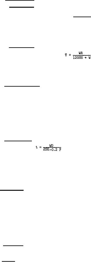
The shell thickness of class 2 tanks shall be determined by the following
formula :
where:
T = Thickness of shell plate in inches.
w = Working pressure p.s.i.g.
R = One half the outside diameter in inches.
3.2.5 Connections (tank).
Piping connections on the tank shall be separate as specified and shall be
as follows:
Air inlet
Air outlet
Relief valve
Drain
Gage
The sizes and locations of the above connections shall be as specified (see 6.1). A pad with 2-inch diam-
eter opening and suitable pad and plate closure shall be provided to permit draining of interior of tank
after galvanizing. This pad shall be so located that other piping connection openings may be used as vents
during drain-off process.
3.2.6 Head thickness.
The thickness of the heads shall be determined by the following formula:
2SEt--
W=
D+0.2 t
where:
t = Minimum required thickness of head after forming in inches. (Exclusive of
corrosion allowance.)
W = Working pressure, p.s.i.g.
D = Inside length of the major axis.
s = Maximum allowable stress value, p.s.i.g. = 13,750.
E = Lowest efficiency of any joint in the head,
3.3 Construction.
3.3.1 The tanks shall consist of a cylindrical shell , closed by convex heads, and shall be all welded.
3.3.2 The nominal plate thickness for heads and shell shall be plus or minus 1/32 inch of the calcu-
lated thickness. The thinning down of the head due to forming shall be not more than 10 percent of the
calculated thickness.
" 3.3.3 Longitudinal seams and girth seams shall be welded. External surfaces of plates at welded
joints shall not be offset from each other. When head skirts are thicker than the shell plate, they shall
be reduced at the joint to approximately the thickness of the shell plate. Forming, including Straight-
ening and matching of plate edges, if done cold , shall be done by steady pressure. Forming by blows may
be done at forging temperature only and shall not damage the surface.
3.3.4 Tank shell. The tank shell shall be made of seamless steel tubing or of steel plate with
welded longitudinal seams (see 3.1), The difference between the largest diameter and smallest diameter of
a shell in any section shall not be greater than 1 percent of the nominal outside diameter.
3.3.5 Heads. Heads shall be convex and shall be made of steel plate as specified in 3.1. Heads
shall be the manufacturer's standard semi-ellipsoidal form, conforming to ASME Boiler and Pressure Vessel
3